Voltage Divider Circuit
Introduction:
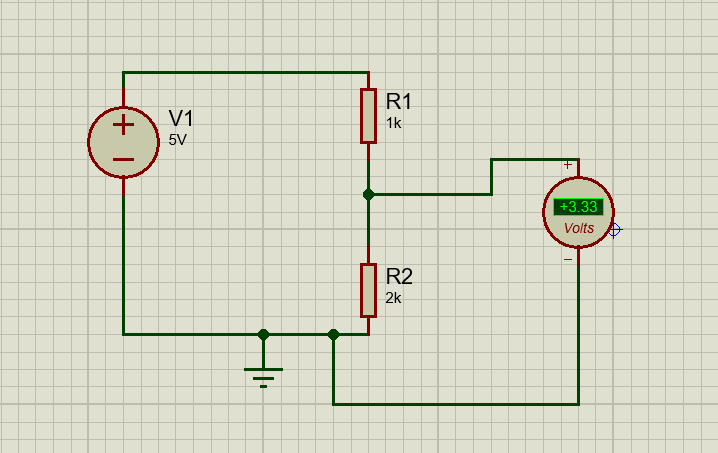
A voltage divider circuit is a simple circuit which turns a large voltage
into a smaller one. Using just two series resistors and an input voltage source,
we can create an output voltage that is a fraction of the input. Voltage
dividers are one of the most fundamental circuits in electronics. Voltage division is the result of distributing the input
voltage among the components of the divider. A simple example of a voltage
divider is two resistors connected in series, with the input voltage
applied across the resistor pair and the output voltage emerging from the
connection between them.

Either R1 or R2 can be
the transducer whose resistance varies with some measured variable. When voltage
divider circuit is used consider the following points.
- The variation of VD with either R1 or R2 is non-linear either even if the resistance varies linearly with measured variable, the divide voltage does not vary linearly.
- The effective output impedance of the divider is the parallel combination of R1 and R2. this is not be high so consider loading effect.

- In this circuit current flows throw both resistor either power will be dissipation by including the transducer must be consider.


