Password Door lock with Arduino Uno

PASSWORD DOOR LOCK PROJECT


In this project you will learn how to make door lock system using Arduino Uno, Keypad Module, Servo Motor and LCD Display in wokwi simulation.

Password door lock codes:

#include <Keypad.h>
#include <LiquidCrystal_I2C.h>
#include <Servo.h>

//Servo Motor
Servo myservo;
int pos=0;

// LCD Part
LiquidCrystal_I2C lcd(0x27,16,2);

// Keypad Module Part
const byte ROWS = 4;
const byte COLS = 4;

char Keys[ROWS][COLS]=
{
  {'1','2','3','A'},
  {'4','5','6','B'},
  {'7','8','9','C'},
  {'*','0','#','D'}
};
byte rowPin[ROWS] = {2,3,4,5};
byte colsPin[COLS] = {6,7,8,9};

Keypad customKeypad = Keypad (makeKeymap(Keys),rowPin,colsPin,ROWS,COLS);

// Door Lock System Part
#define Password_Lenght 7
char Data[Password_Lenght]; // 6 is the number of chars it can hold + the null char = 7
char Master[Password_Lenght] = "123456";
byte data_count = 0, master_count = 0;
char customKey;


bool door = true;

void setup() {
  // put your setup code here, to run once:
  lcd.init();
  lcd.backlight();
  myservo.attach(10);

}

void loop() {
  // put your main code here, to run repeatedly:
  if (door == 0)
  {
    customKey = customKeypad.getKey();

    if (customKey == '#')

    {
      lcd.clear();
      ServoClose();
      lcd.print("  Door is close");
      delay(3000);
      door = 1;
    }
  }

  else Open();
}

void Open()
{
  lcd.setCursor(0, 0);
  lcd.print(" Enter Password");
 
  customKey = customKeypad.getKey();
  if (customKey) // makes sure a key is actually pressed, equal to (customKey != NO_KEY)
  {
    Data[data_count] = customKey; // store char into data array
    lcd.setCursor(data_count, 1); // move cursor to show each new char
    lcd.print(Data[data_count]); // print char at said cursor
    data_count++; // increment data array by 1 to store new char, also keep track of the number of chars entered
  }

  if (data_count == Password_Lenght - 1) // if the array index is equal to the number of expected chars, compare data to master
  {
    if (!strcmp(Data, Master)) // equal to (strcmp(Data, Master) == 0)
    {
      lcd.clear();
      ServoOpen();
      lcd.print("  Door is Open");
      door = 0;
    }
    else
    {
      lcd.clear();
      lcd.print("  Wrong Password");
      delay(1000);
      door = 1;
    }
    clearData();
  }
}
void clearData()
{
  while (data_count != 0)
  { // This can be used for any array size,
    Data[data_count--] = 0; //clear array for new data
  }
  return;
}
void ServoOpen()
{
  for (pos = 180; pos >= 0; pos -= 5) { // goes from 0 degrees to 180 degrees
    // in steps of 1 degree
    myservo.write(pos);              // tell servo to go to position in variable 'pos'
    delay(15);                       // waits 15ms for the servo to reach the position
  }
}
void ServoClose()
{
  for (pos = 0; pos <= 180; pos += 5) { // goes from 180 degrees to 0 degrees
    myservo.write(pos);              // tell servo to go to position in variable 'pos'
    delay(15);                       // waits 15ms for the servo to reach the position
  }
}
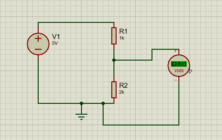


Voltage Divider Circuit

 Voltage Divider Circuit

Introduction:

voltage divider circuit is a simple circuit which turns a large voltage into a smaller one. Using just two series resistors and an input voltage source, we can create an output voltage that is a fraction of the input. Voltage dividers are one of the most fundamental circuits in electronics. Voltage division is the result of distributing the input voltage among the components of the divider. A simple example of a voltage divider is two resistors connected in series, with the input voltage applied across the resistor pair and the output voltage emerging from the connection between them.

consider a voltage divider circuit as shown in figure.


This can be used to provide conversion of resistance variation into a voltage variation. the voltage of such a divider is given by the well-known relationship.
the voltage VD across R2 is given as


where

Vs = supply voltage
R1, R2 = Divider resistor

Either R1 or R2 can be the transducer whose resistance varies with some measured variable. When voltage divider circuit is used consider the following points.

  1. The variation of VD with either R1 or R2 is non-linear either even if the resistance varies linearly with measured variable, the divide voltage does not vary linearly.
  2. The effective output impedance of the divider is the parallel combination of  R1 and R2. this is not be high so consider loading effect.                                                                                                                                               

  3. In this circuit current flows throw both resistor either power will be dissipation by including the transducer must be consider.                                                                                                                                                                       


Level Control Circuit

 Level Control circuit in Proteus

Description:
level control circuit is made up of different components as shown in figure basically it is main purpose to maintain the level of any tank or keep the level at a set point the ultrasonic sensor detects the level of the tank and generate the output signal gives to the Arduino Uno controller input pin. The controller generates the output signal as per the algorithm to the user define set point then 5volt relay operates in the controller output signal to on-off the motor.

Components: 
1.Arduino Uno
2.LCD display LM061L
3.Motor
4.Relay (5volt)
5.Potantiometer as POT-HG
6.Ultrasonic sensor

Software:
1.Arduino IDE
2.Programing


Programing:’
# include "LiquidCrystal.h"  //lcd libary     
LiquidCrystal lcd(2, 3, 4, 5, 6, 7);   //LCD object Parameters: (rs, enable, d4, d5, d6, d7)
const int trigPin = 12; //trig pin connection
const int echoPin = 11;  //echopin connection
long duration;
int distanceCm;
float liquid;
void setup() {      // setup perameter
lcd.begin(16,2);                                                  
pinMode(trigPin, OUTPUT);
pinMode(echoPin, INPUT);
pinMode(8,OUTPUT);
lcd.setCursor(0,0);
lcd.print("  Distance    ");
lcd.setCursor(0,1);
lcd.print("  Measurement  ");
delay(2000);
lcd.clear();
lcd.setCursor(0,0);
lcd.print("    Made By    ");
lcd.setCursor(0,1);
lcd.print("rf230");
delay(2000);
lcd.clear();
}
 
void loop() {   // loop of flow program
digitalWrite(trigPin, LOW);
delayMicroseconds(2);
digitalWrite(trigPin, HIGH);
delayMicroseconds(10);
digitalWrite(trigPin, LOW);
duration = pulseIn(echoPin, HIGH);
distanceCm= duration*0.034/2;                                                                                
lcd.setCursor(0,0);                                                
lcd.print("Distance Measur.");
delay(10);
lcd.setCursor(0,1);
lcd.print("Distance:");
lcd.print(distanceCm);
lcd.print(" Cm ");
delay(10);
if(distanceCm<=500)
{
  digitalWrite(8,HIGH);
}
else if(distanceCm>=1000)
{
  digitalWrite(8,LOW);
}
}


Notes: you make sure that the require library you have already download as "LiquidCrysrtal.h". go to tool bar select manage libraries then search LiquidCrysrtal.h and click on install button.


SPI Communication between two Arduino Uno

 What Is SPI Communication SPI (Serial Peripheral Interface) communication is a synchronous serial communication protocol used primarily for...